Darlington Pair Circuit Diagram
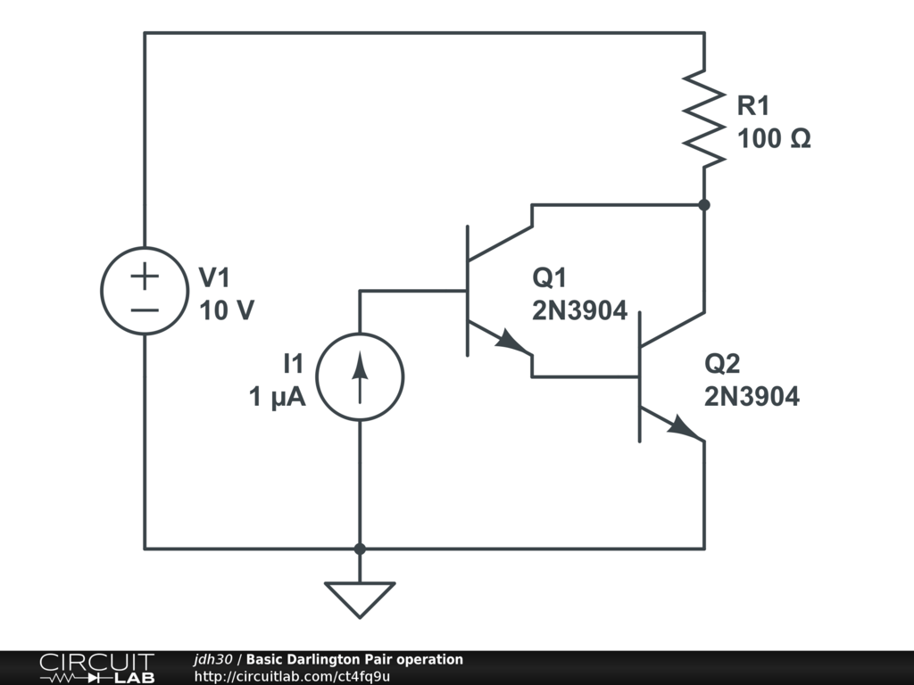
Web in this article we understand the faction circuit diagram and application of darlington pair. With the multimeter you measure the voltage between the base of transistor t1 and the emitter of transistor t2. If we see the darlington transistor’s symbol we can clearly see how two transistors are connected. 1 shows a schematic diagram with transistors and connected as a darlington transistor pair.
Darlington Pair Darlington Pair Uln2803 Driver Tinkercad If The
Measuring the voltage u be of a. The way they work is easier to understand if it is explained in terms of conventional current. The two transistors amplify the weak current in the circuit allowing.
A Very Popular Connection Of Two Bjts For Operation As One “Superbeta” Transistor Is The Darlington Connection.
Analog, digital, or mixed analog and digital system requires amplifier [1] [2] [4]. The darlington transistor is invented by sidney darlington. Web the darlington transistor, or more commonly, the darlington pair, consists of two separate bipolar transistors sharing a common collector, and when combined, offer an.
Web In This Video, What Is Darlington Pair, The Applications Of The Darlington Pair, The Advantage And Disadvantages Of The Darlington Pair Are Explained.
Sometimes, this circuit is called the super alpha pair circuit. Web darlington pair or darlington transistor is one of them. Web darlington transistor pair and its configuration:
Web These Transistor Pairs Are Used In Amplification Circuits Where The Gain Required Being High.
Sometimes you want to control a really large amount of current; Is one of the most important concept and application of electronic, almost all electronic; More than a single transistor's gain can provide.
The Darlington Pair Has Two Transistors Connected In A Way So That It Provides A High.
The above are the some of the applications of the darlington pair. Web a darlington pair consists of two npn transistors connected as shown in the diagram. Web the two transistors are known as a darlington pair.
The Output Current Has To Be.
Web december 3, 2010 rend this a circuit of the darlington pair, on of popular transistor circuit configurations. Darlington pair of two transistors. Without a darlington pair the circuit would probably fail.
Here, T 1 And T 2 Are The Two Transistors.
Web the darlington pair can be made from two transistors as shown in the diagram or darlington pair transistors are available where the two transistors are. Web build the circuit shown. The emitter terminal of the first transistor (t1) is.
Web Build The Circuit Shown That Now Contains Two Transistors.


