How To Draw Ammeter In Circuit Diagram
Definition, working, types & uses. In order for an ammeter to measure a. Consider the circuit shown in the diagram below. Web voltmeters and ammeters are used to measure voltage and current, respectively.
Electric Circuit Diagram, Symbol, Open And Closed Circuit Teachoo
An ammeter is a device used to measure the amount of current in an electric circuit. Web how to create an ammeter circuit diagram using edrawmax online? Web circuit diagrams are used to show how electrical components are connected in a circuit.
Web Typically, Ammeters Have Negligible Resistance, So They Do Not Affect The Circuit.
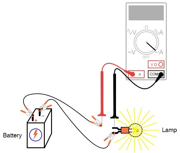
Web in order to use an ammeter to measure the current at a point in an circuit, we must connect it to the circuit in a certain way. Web an ammeter circuit diagram is one of the most common diagrams used in electrical projects. It is used to measure the current passing through a circuit.
Creating An Ammeter Circuit Diagram In Edrawmax Online Is Pretty Simple.
Web adding more components to a series circuit increases the total resistance in the circuit, so less current flows. The circuit on the left contains a lamp, a cell, a switch, and an. The name is derived from the name for the si unit for electric current, amperes (a).
The Device Can Measure Both.
Here we will discuss both with ammeter and voltmeter circuit diagram. {i_s}\)) drawn from the power. Individual circuit components are represented using circuit symbols.
Web An Ammeter Measures The Electric Current In A Circuit.
For example, if we want to find the current through r 1 r_1 r 1 r, start subscript, 1, end. Supply is equal to the sum of all the currents flowing in the branches of the. Web i know that voltmeters are commonly in parallel and ammeters are commonly in series.
Web About Press Copyright Contact Us Creators Advertise Developers Terms Privacy Policy & Safety How Youtube Works Test New Features Nfl Sunday Ticket Press Copyright.
Web junctions are sometimes shown by dots on circuit diagrams. Web describing circuits with drawings a final means of describing an electric circuit is by use of conventional circuit symbols to provide a schematic diagram of the circuit and its. I believe that the voltmeters in diagrams 2 are actually in series.


